Crank Trigger
This page provides detailed information about the OEM Crank Trigger (TRIG) sensor (also called the 'Ignition Pulse Generator') used in the Honda RC51, including its specifications, connector details, visual references, and technical documentation.
TRIG Description
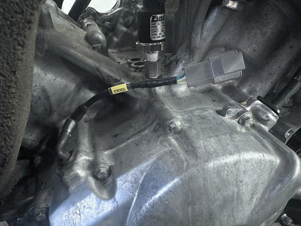
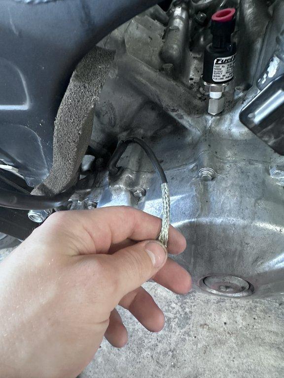
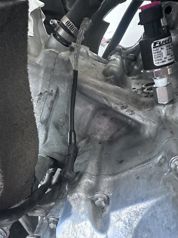
The Honda RC51 (RVT1000R) utilizes a 2-pin Variable Reluctance (VR) sensor as its OEM crank trigger. Notably, both this sensor and the CAM Sync sensor are unshielded in the factory configuration. Honda engineers likely optimized the wiring routing to minimize electromagnetic interference without shielding. However, adding shielding can enhance signal integrity and reduce noise. Instead of opening the crankcase to shield the complete length of the sensor wires, I opted to apply braided shielding over the leads exiting the crankcase. I used 1/8" tinned copper metal braid sleeving, purchased from Amazon here. While ideally the entire length of the wires should be shielded, this partial shielding is an improvement over the unshielded OEM setup, and no significant interference sources are present in the unshielded sections. A solder seal was used to pass the shielding through a DTM connector with a 22-gauge TXL wire. The leads and sleeving were sealed with Raychem DR-25 heat-shrink tubing and SCL encapsulant at both ends for durability and protection.
Connector Data
OEM connector specifications for the crank trigger sensor will be updated in the future. For my custom application, I used a DTM04-3P connector to ensure a robust and weather-sealed connection.
Proper pin assignment is critical for the VR sensor, as incorrect connections can lead to erratic ECU readings. Refer to the Sensors Sub-Harness page for a detailed wiring diagram.
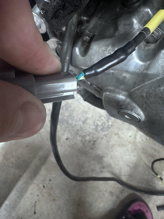
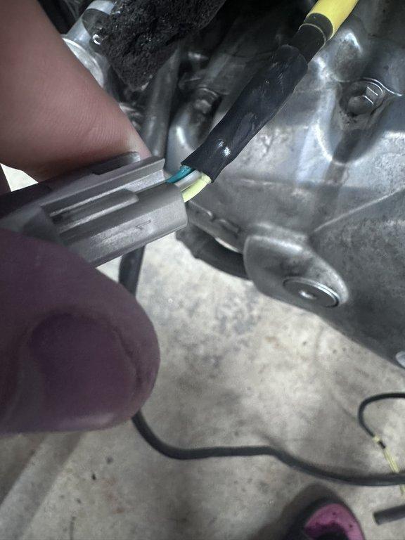
Observe the images below; the YELLOW wire from the OEM leads on the crank trigger is the signal wire and should connect to Pin 19 on Connector A of the FT550. The WHITE/YELLOW wire is the negative for the VR sensor and should be connected to Pin 18 on Connector A of the FT550. Both wires should remain shielded until grounded at the ECU side.

Additional Notes: When installing or modifying the crank trigger sensor wiring, ensure the shielding is properly grounded to prevent noise interference. Use high-quality, fuel- and heat-resistant materials for all connections, and verify continuity with a multimeter after installation to confirm signal integrity. Shielding should only be grounded at the ECU side for this sensor.
ECU Setup
ECU configuration details for the crank trigger sensor will be provided in a future update. Ensure the ECU is programmed to recognize the VR sensor’s signal characteristics, including polarity and trigger pattern.
Crank Trigger Sensor Images