OEM Fuel Injector Harness
OEM Fuel Injector Harness Guide
This guide provides an overview of the OEM fuel injector sub-harness, lists common connectors used, and outlines steps to build a new harness that replicates the OEM design.
OEM Fuel Injector Sub-Harness Description
The Honda RC51 OEM fuel injector harness connects the following sensors to the ECU:
| Sensor Name | Description | Connector Type |
|---|---|---|
| MAP Sensor | Measures manifold absolute pressure. | Sumitomo 6189-0154 |
| Throttle Position Sensor (TPS) | Monitors the throttle valve position. | Sumitomo 6189-0154 |
| Injector 1-1 | Fuel injector for Rear, primary | Sumitomo 6195-0043 |
| Injector 1-2 | Fuel injector for Rear, secondary | Sumitomo 6195-0043 |
| Injector 2-1 | Fuel injector for Front, primary | Sumitomo 6195-0043 |
| Injector 2-2 | Fuel injector for Front, secondary | Sumitomo 6195-0043 |
Note that in the wiring diagram, Honda designates the rear cylinder as cylinder #1 and the front as cylinder #2. This is reflected physically on the sub-harness, where the rear injector connectors are labeled '1' and have corresponding wire colors. This is unusual, as the firing order is front-rear, so typically the first-firing cylinder would be labeled #1. However, based on my research and the Service Manual, Honda chose a different convention. If referring to the Custom FISH harness section, note that I designate the front cylinder as #1 and the rear as #2. To avoid confusion, it’s best to refer to them as Front Primary, Front Secondary, etc.


Here is the OEM wiring diagram snippet outlining the fuel injector sub-harness:
.png)
OEM vs Custom Sub-Harness
Personally, I’m not a fan of the electrical tape used in many OEM harnesses, and the FISH was no exception. I decided to make a custom FISH since the FT550 has an internal MAP sensor, but the OEM harness would work. However, I went through the trouble of identifying all the connectors on the harness so you can create one if desired. Check out the individual pages for the TPS sensor and injectors for more information on the connectors those components use and where to source them. The main 10P connector is defined here.
If you use the OEM FISH, leave the MAP sensor connector unplugged if you’re not using it, as in my case. I also decided to attach a fuel pressure sensor at a different location on the main harness (actually the Sensors sub-harness). This was because the harness would need to cross the throttle bodies, as the fuel pressure sensor is on the opposite side from the FISH. This way, the OEM FISH can be used if desired.
Main Connector on the FISH
As mentioned previously, check out the individual pages on the TPS and injectors for more information on the connectors those components use. This page only covers the 10-pin sub-harness connector that connects this sub-harness to the main harness.
Here is the main OEM connector pin layout for this sub-harness:

The following is the pinout of the OEM FI harness, including color code:
| Pin Location | Color | Use | Wire Gauge |
|---|---|---|---|
| 1 | Yellow/Red (stripe) | +5V | 20 |
| 2 | Red/Yellow (stripe) | TPS Signal | 22 |
| 3 | Green/Orange (stripe) | Sensor Ground | 20 |
| 4 | Pink | Injector 1-1 (Rear Primary) | 22 |
| 5 | Pink/Blue (stripe) | Injector 1-2 (Rear Secondary) | 22 |
| 6 | (none) | empty | (none) |
| 7 | Light Green/Yellow (stripe) | MAP Signal | 22 |
| 8 | Pink/Green (stripe) | Injector 2-1 (Front Primary) | 22 |
| 9 | Black/White (stripe) | +12V | 20 |
| 10 | Pink/Black (stripe) | Injector 2-2 (Front Secondary) | 22 |
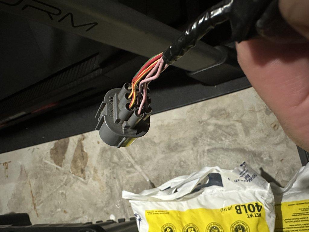
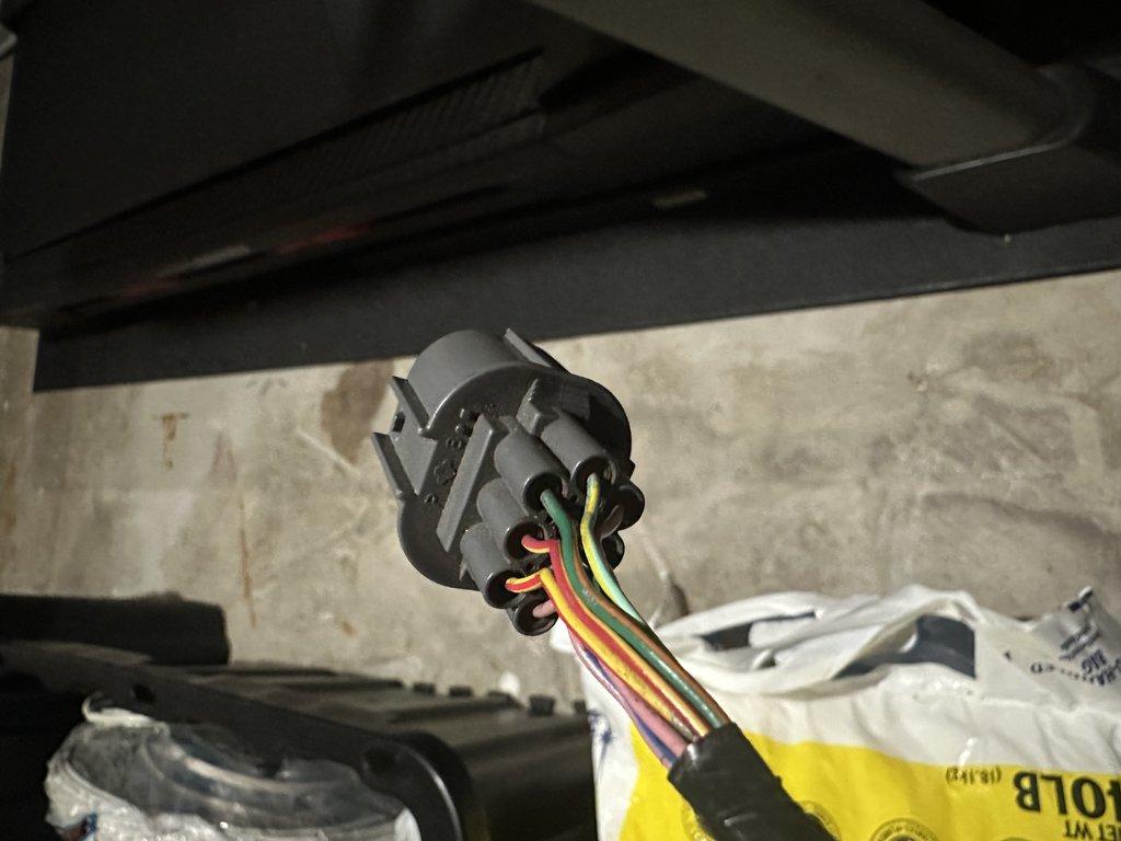
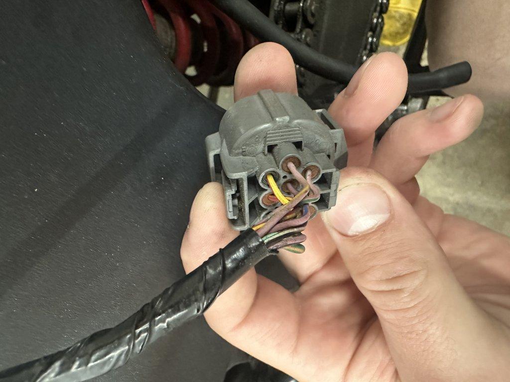
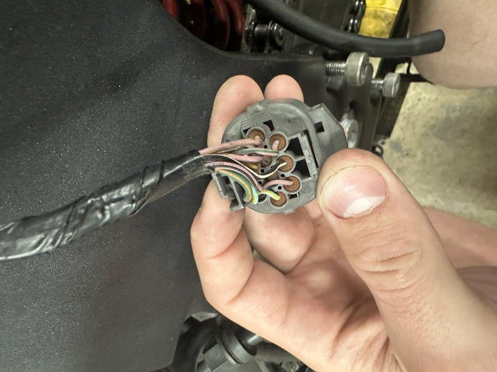
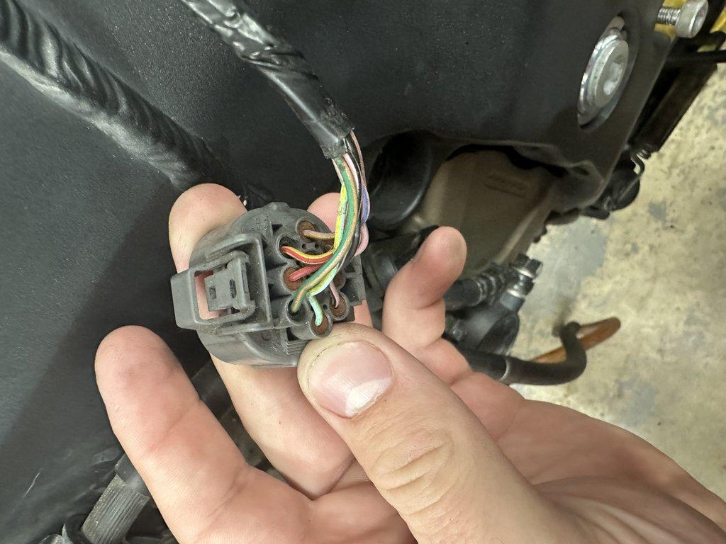
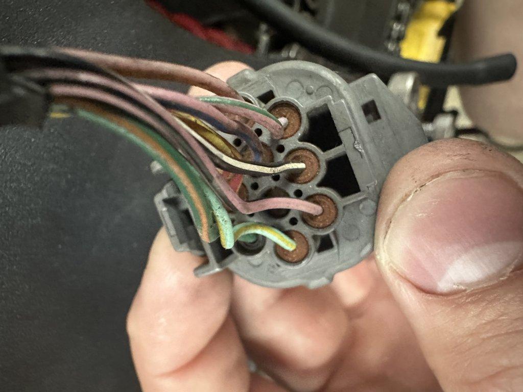
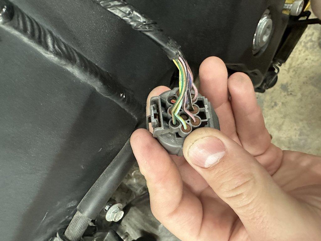
For reference, here are some images of the physical male connector located on the FI sub-harness:
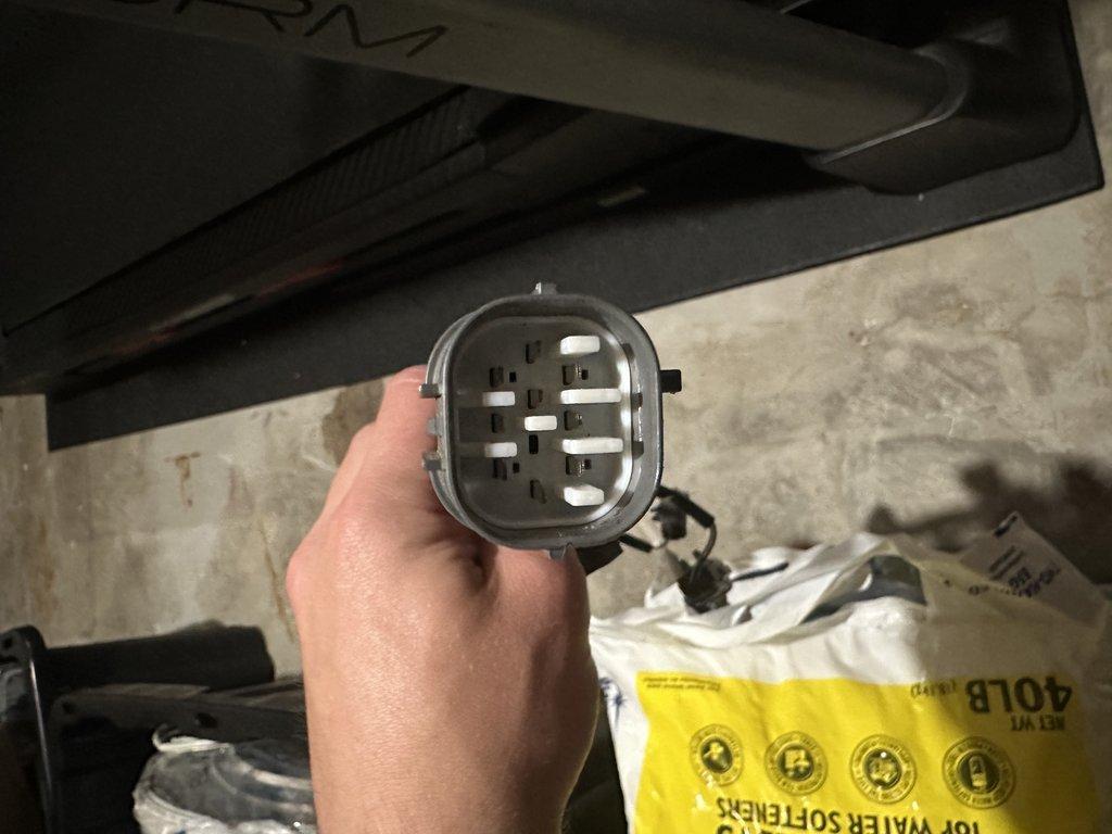
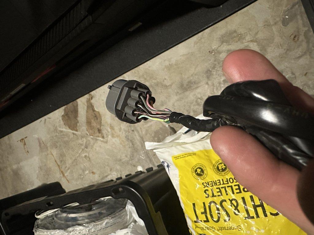
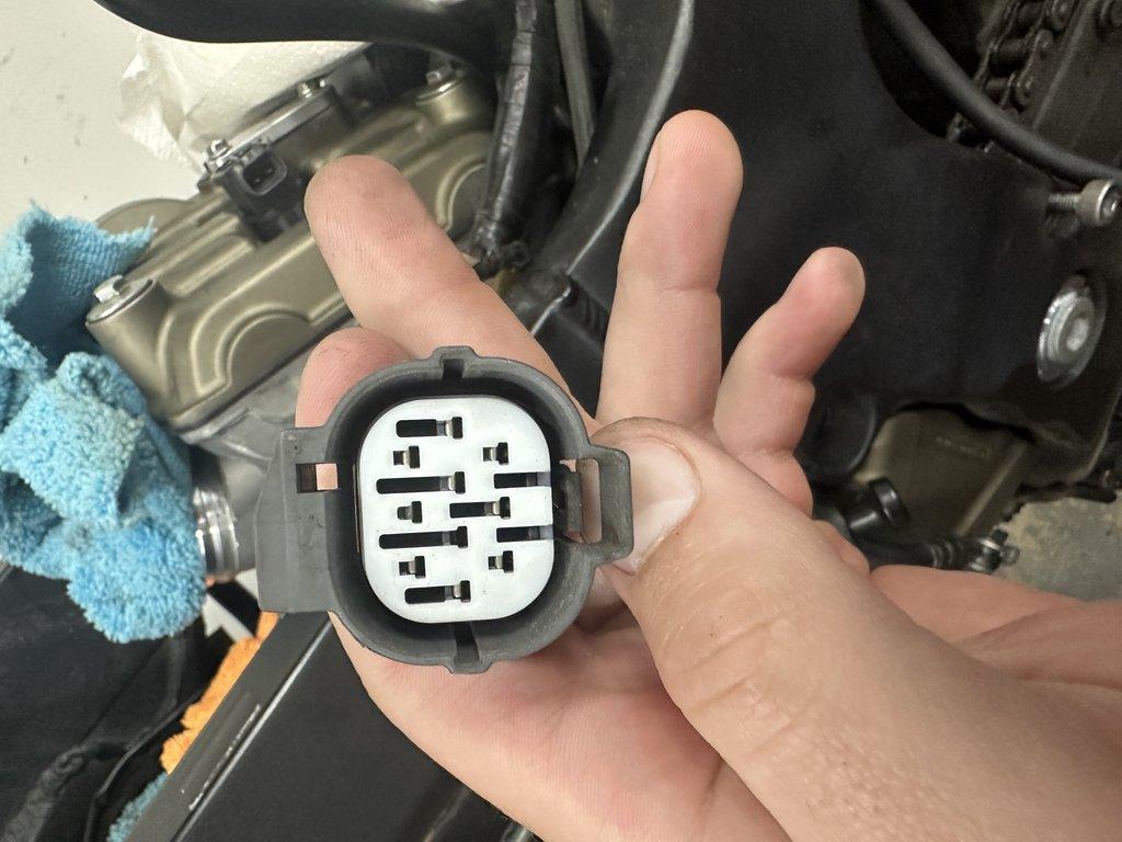
Here are some images of the physical female connector located on the main harness and the actual housing you will need to source for your new main harness:
Sourcing the Main Connector
This connector is a Sumitomo HW Sealed Series, 10-pin. Refer to the table below for data on the male and female connectors. If you are using the OEM FI sub-harness, you need the connector that is on the OEM main harness, which is the female housing.
| Way | Sumitomo Part Number | Model | Info |
|---|---|---|---|
| Male | 6181-0076 | HW-10P | Info |
| Female | 6189-0135 | HW-10S | Info |
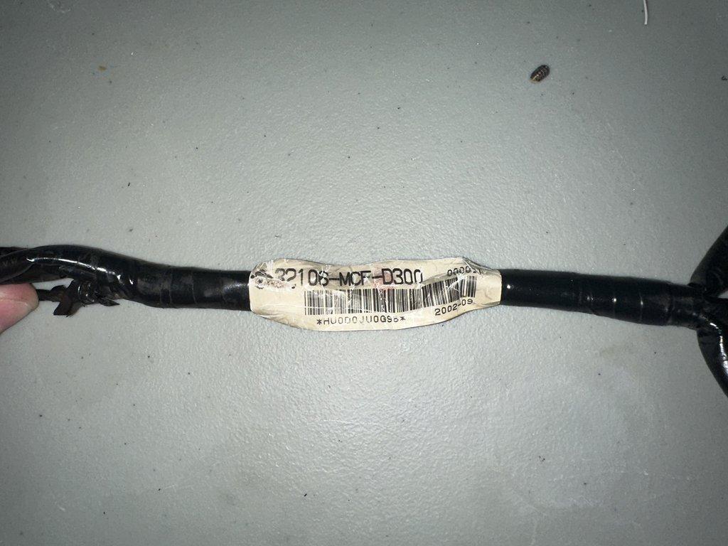
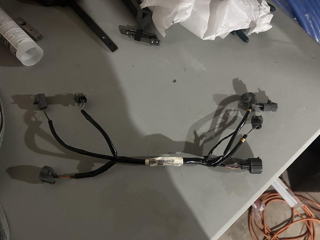
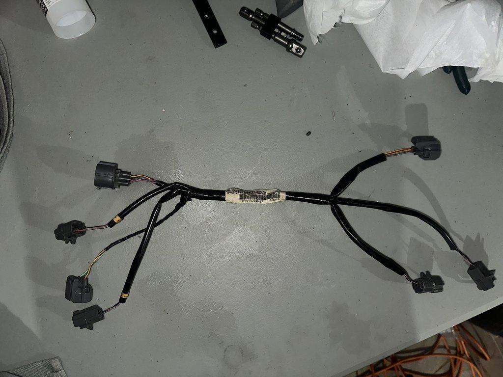
OEM Harness Images