OEM Left Handlebar Controls
Left Handlebar Controls
Originally, I intended to create custom left and right handlebar controls. That’s still the plan, but to get the motorcycle up and running quickly, I modified the OEM switches to meet my needs for now. Below is a brief overview of the left-hand handlebar controls.
As always, if you need further clarification or have any questions, reach out.
Wiring
Using the stock wiring, I removed the turn signal running light wires and their power lead, sealing off the wire ends. I didn’t remove them completely from the switch assembly, as they appeared soldered and coated with insulation. Most of the wiring remains OEM, but the horn switch was repurposed as an ECU-switched input, which I plan to use for a two-step function or datalog button. That is the nice thing about a conigurable ECU, I can set it up as one thing and change it later if needed.
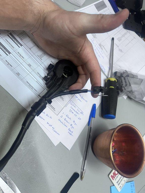
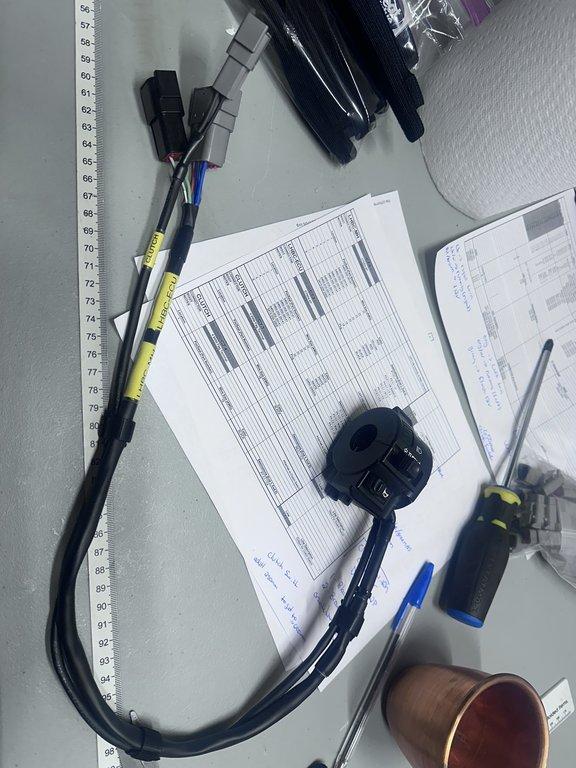
For the clutch switch, I extended the leads from the Ducati clutch switch to match the length of the RC51 LH control leads. It’s important to leave enough slack in the clutch switch leads from the LH controls so each can be removed independently.
Ducati Clutch Switch
There may be concern regarding the wire gauge used for the Ducati clutch switch. Approximately 3–4 amps will flow through these wires from the starter relay coil. While 22 AWG wire has a theoretical maximum capacity of 7 amps, bundling and length reduce this. In my case, a safe maximum is about 5 amps.
The run is very short and it would only be used during starting, so I don’t anticipate any issues, but it’s worth noting. If problems arise later, I’ll update this section accordingly.
Turn Signal Logic
As mentioned in the Power Supply section, I planned to use latching switches in the custom LHB controls. Since I’ll eventually replace the OEM controls, I implemented the same logic using the modified OEM switches.
The OEM turn signal switch only allows one position at a time—left or right. Regardless, each turn signal sends 24V back to the power supply, activating the appropriate relay in the fuse and relay box.
Reference Documents
Left Handlebar Controls Images
Explore this collection of images showcasing the modified OEM left handlebar controls. NOTE: these images show my first released version of these controls. Since I decided against using multiple switches in the LHBC, there was no need to keep the larger connectors on. Instead I combined the clutch leads into the other Main Harness connector and converted the ECU harness connector to a 2 pin connector instead. All wiring (except these connector ends) remains the same. I have updated all diagrams to reflect this change, but the images may still be version 1 release.