Power Supply - 24V PSU
This guide details the 24V power supply used in the Honda RC51 ECU build to drive relay coils for the custom left-hand handlebar switch logic, including design rationale and selection criteria.
Design Rationale
As part of my custom left-hand handlebar switch design, I incorporated two latching switches for turn signal control. While this added complexity, it allowed for a unique logic implementation where only one turn signal can be active at a time. More details on this logic can be found in the LH Switch section.
To achieve this behavior, I used two 5-pin relays with their coils wired in series. This configuration required either:
- Two 6V relays powered by a 12V source
- Two 12V relays powered by a 24V source
I opted for the latter, using a 24V power supply to drive the relay coils. While not the cleanest solution, it allowed me to maintain consistent relay form factors across the system. A Power Management Unit (PMU) could have simplified this, but I chose to work within the constraints of my design.
Do not use relays with built-in diodes or resistors in this configuration, as they will short-circuit when wired in this logical format. Ensure relays are rated for 12V coil operation and free of internal suppression components. Use crimp terminals and proper strain relief to prevent vibration-related failures.
Selecting a 24V Power Supply
Since the 24V supply is only used to power the relay coils, current requirements are minimal. A compact, regulated supply rated for 0.5–1A is sufficient. DIN-rail mounted or enclosed DC-DC converters are ideal for integration into the power distribution system.
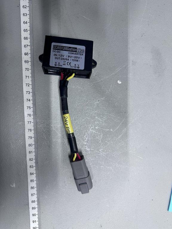
24V Power Supply Images
Explore this image showcasing the 24V power supply.