Transmission RPM
This guide details the Driveshaft RPM sensor, also known as the vehicle speed sensor, used in my Honda RC51 custom ECU build, including its specifications, connector details, wiring, ECU setup in FT Manager, and visual references.
Driveshaft RPM Sensor Overview
The Driveshaft RPM sensor allows the FT550 ECU to determine vehicle speed by monitoring the rotation of the driveshaft. In my RC51 build, this sensor enables features like speed-based tuning and traction control. It's a Hall Effect sensor that outputs a 5V digital square wave signal proportional to shaft speed.
Driveshaft RPM Sensor Specifications
The OEM Honda RC51 Driveshaft RPM sensor is mounted near the counter-shaft and reads from a gear with 27 teeth, generating 27 pulses per revolution, as noted in the Speedzilla post here.
Connector Data
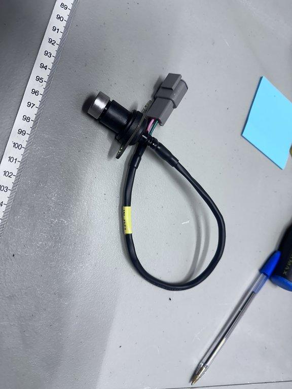
For my build, I replaced it with a DTM04-3P connector to match my custom harness. I'll update the OEM connector specifications later.
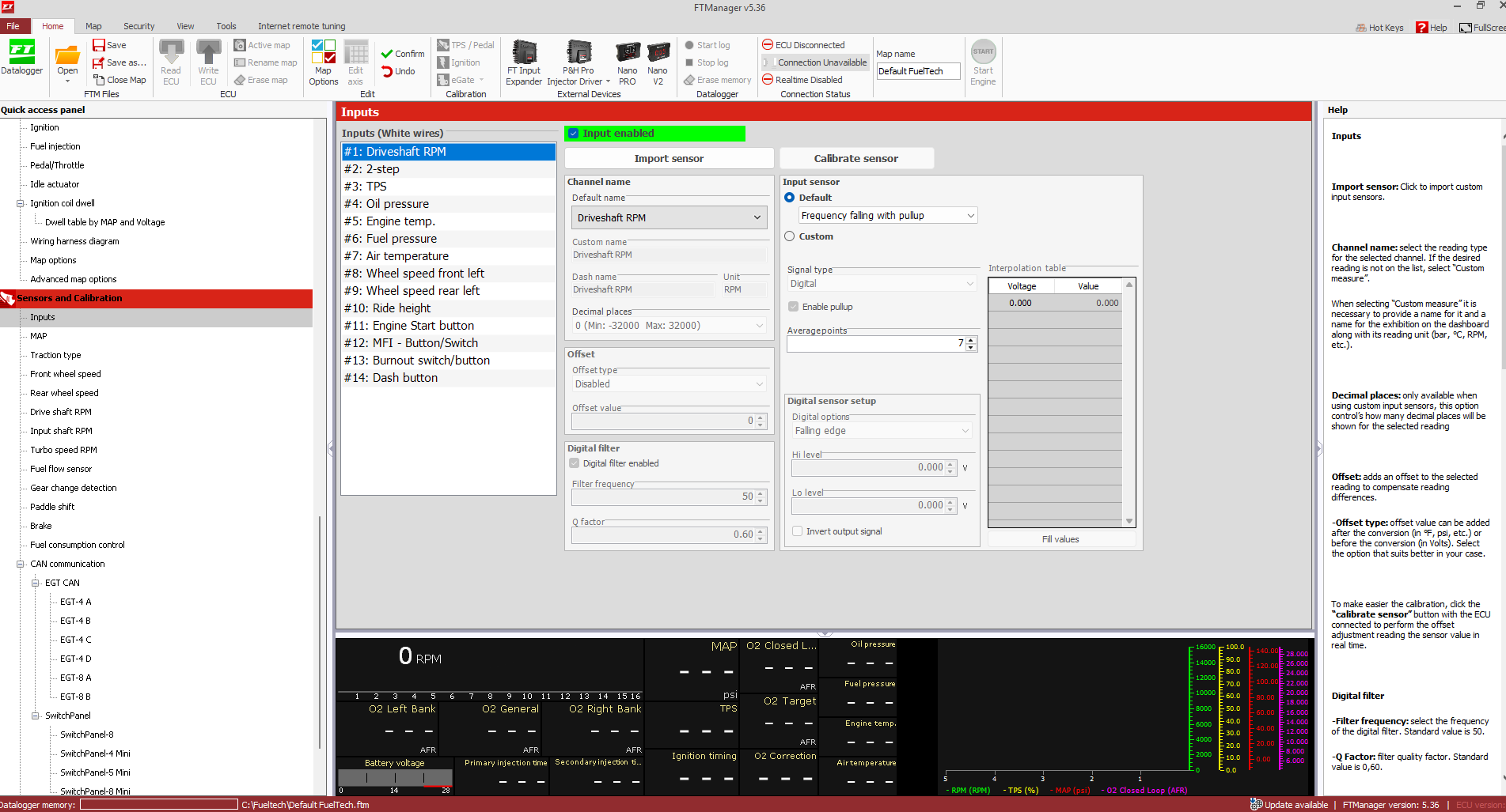
ECU Setup in FT Manager
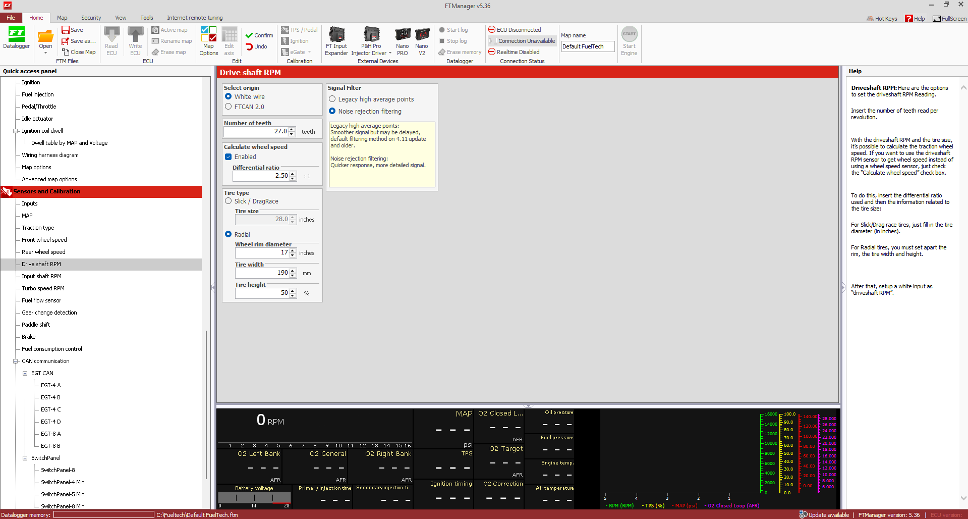
Configure the sensor in FT Manager under Sensors and Calibration > Inputs. Select a white input for "Driveshaft RPM" and set it as a Hall Effect sensor. Input the pulse count: 27 pulses per revolution for the RC51 output shaft. Additionally, configure the differential ratio and tire specifications to ensure accurate speed calculations.
FT Manager must be configured to match the rear tire size and sprocket setup for accurate speed calculation. Use the tire circumference (190/50 R17) and final drive ratio (16F/40R sprockets = 2.5) in the vehicle speed settings which are the stock values as a referance.
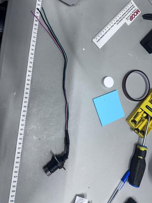
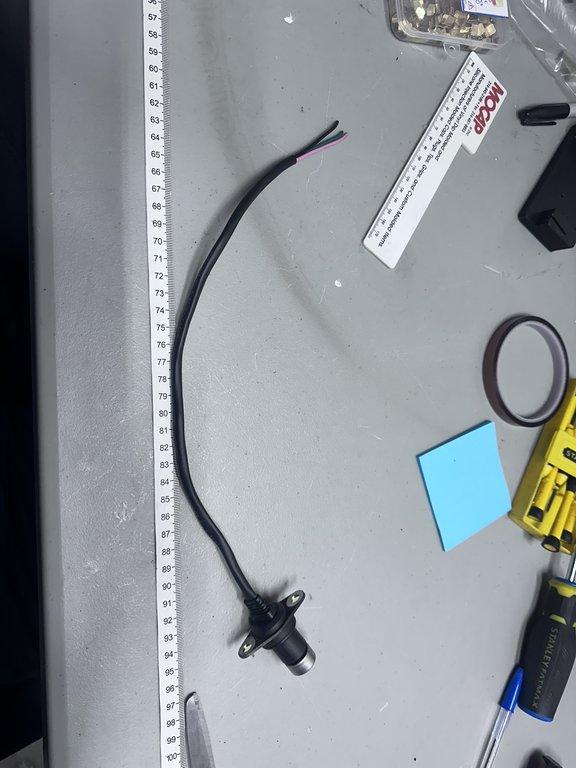
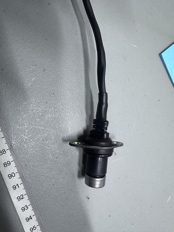
Driveshaft RPM Sensor Images